| Items |
 /Asset/Cylindrical-Inductive-Proximity-Sensors.png /Asset/Cylindrical-Inductive-Proximity-Sensors.png PR PR Series Cylindrical Inductive Proximity Sensor |
 /Asset/Cylindrical-Inductive-Long-Distance-Proximity-Sensors.png /Asset/Cylindrical-Inductive-Long-Distance-Proximity-Sensors.png PRD PRD Series Cylindrical Inductive Long-Distance Proximity Sensor |
 /Asset/Cylindrical-Inductive-Full-Metal-Proximity-Sensors.png /Asset/Cylindrical-Inductive-Full-Metal-Proximity-Sensors.png PRF PRF Series Cylindrical Inductive Full-Metal Proximity Sensor |
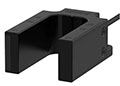 /Asset/MU-Series-U-Shaped-Magnetic-Proximity-Sensors.jpg /Asset/MU-Series-U-Shaped-Magnetic-Proximity-Sensors.jpg MU MU Series U-Shaped Magnetic Proximity Sensor |
 /Asset/Cylindrical-Inductive-Full-Metal-Long-Distance-Proximity-Sensors.png /Asset/Cylindrical-Inductive-Full-Metal-Long-Distance-Proximity-Sensors.png PRFD PRFD Series Cylindrical Inductive Full-Metal Long-Distance Proximity Sensor |
|||||
| Description | ||||||||||
| Brands |
Autonics |
|||||||||
| Model | PR | PRD | PRF | MU | PRFD | |||||
| Type | Sensor | |||||||||
| Power Supply | 12 - 24 VDC (ripple P-P: ≤ 10 %), operating voltage: 10 - 30 VDC | 12 - 24 VDC (ripple P-P: ≤ 10 %), operating voltage: 10 - 30 VDC | 12 - 24 VDC (ripple P-P: ≤ 10 %), operating voltage: 10 - 30 VDC | 12 - 24 VDC (ripple P-P: ≤ 10 %), operating voltage: 10 - 30 VDC | ||||||
| Leakage Current | ≤ 0.6 mA | ≤ 0.8 mA | ≤ 0.8 mA | |||||||
| Current Consumption | ≤ 10 mA | |||||||||
| Control Output | 2 to 100 mA | ≤ 200 mA | 3 to 100 mA | 3 to 100 mA | ||||||
| Residual Voltage | ≤ 3.5 V (non-polarity 01): ≤ 5 V) |
Diameter of sensing side Ø 8mm: ≤ 2 V Diameter of sensing side Ø 12 mm, Ø 18 mm, Ø 30 mm: ≤ 1.5 V |
≤ 3.5 V | ≤ 3.5 V | ||||||
| Protection Circuit | Surge protection circuit, output short over current protection circuit, reverse polarity protection | Surge protection circuit, output short over current protection circuit, reverse polarity protection | Surge protection circuit, output short over current protection circuit, reverse polarity protection | Surge protection circuit, output short over current protection circuit, reverse polarity protection | ||||||
| Insulation Resistance | ≥ 50 MΩ (500 VDC megger) | ≥ 50 MΩ (500 VDC megger) | ≥ 50 MΩ (500 VDC megger) | ≥ 1,000 MΩ (500 VDC megger) | ≥ 50 MΩ (500 VDC megger) | |||||
| Dielectric Strength | Between the charging part and the case: 1,500 VAC 50/60 Hz for 1 minute | Between the charging part and the case: 1,000 VAC 50/60Hz for 1 minute | Between the charging part and the case: 500 VAC~50/60 Hz for 1 minute | Between the charging part and the case: 1,000 VAC 50/60Hz for 1 minute | ||||||
| Vibration | 1 mm double amplitude at frequency 10 to 55 Hz in each X, Y, Z direction for 2 hours | 1 mm double amplitude at frequency 10 to 55 Hz in each X, Y, Z direction for 2 hours | 1.5 mm amplitude at frequency 10 to 55 Hz in each X, Y, Z direction for 2 hours | 1.5 mm double amplitude at frequency of 10 to 55 Hz in each X, Y, Z | 1.5 mm double amplitude at frequency 10 to 55 Hz in each X, Y, Z direction for 2 hours | |||||
| Shock | 500 m/s² (≈ 50 G) in each X, Y, Z direction for 3 times | 500 m/s² (≈ 50 G) in each X, Y, Z direction for 3 times | 100 m/s² (≈ 10 G) in each X, Y, Z direction for 3 times | |||||||
| Ambient Temperature | -25 to 70 ºC, Storage: -30 to 80 ºC (No Freezing or Condensation) | -25 to 70 ºC, Storage: -30 to 80 ºC (No Freezing or Condensation) | -25 to 70 ºC, Storage: -25 to 70 ºC (No Freezing or Condensation) | -10 to 65 ºC, Storage: -10 to 70 ºC (No Freezing or condensation | -25 to 70 ºC, Storage: -25 to 70 ºC (No Freezing or Condensation) | |||||
| Note for Ambient Temperature | Underwriters Laboratories (UL) approved surrounding air temperature 40 ºC | Underwriters Laboratories (UL) approved surrounding air temperature 40 ºC | ||||||||
| Ambient Humidity | 35 to 95% RH, Storage: 35 to 95% RH (No Freezing or Condensation) | 35 to 95% RH, Storage: 35 to 95% RH (Non-Freezing or Non-Condensation) | 35 to 95% RH, Storage: 35 to 95% RH (Non-Freezing or Non-Condensation) | 35 to 85% RH, storage : 35 to 85% RH (No freezing or Condensation) | 35 to 95% RH, Storage: 35 to 95% RH (No Freezing or Condensation) | |||||
| Connection | Cable Connector Type Cable Type Connector Type Model | Cable Connector Type Cable Type | Cable Connector Type Cable Type | Cable Connector Type Cable Type | ||||||
| Connector Specification | M12 connector | M12 connector | M12 connector | |||||||
| Features |
|
|
|
|
|
|||||
|
|
||||||||||

